
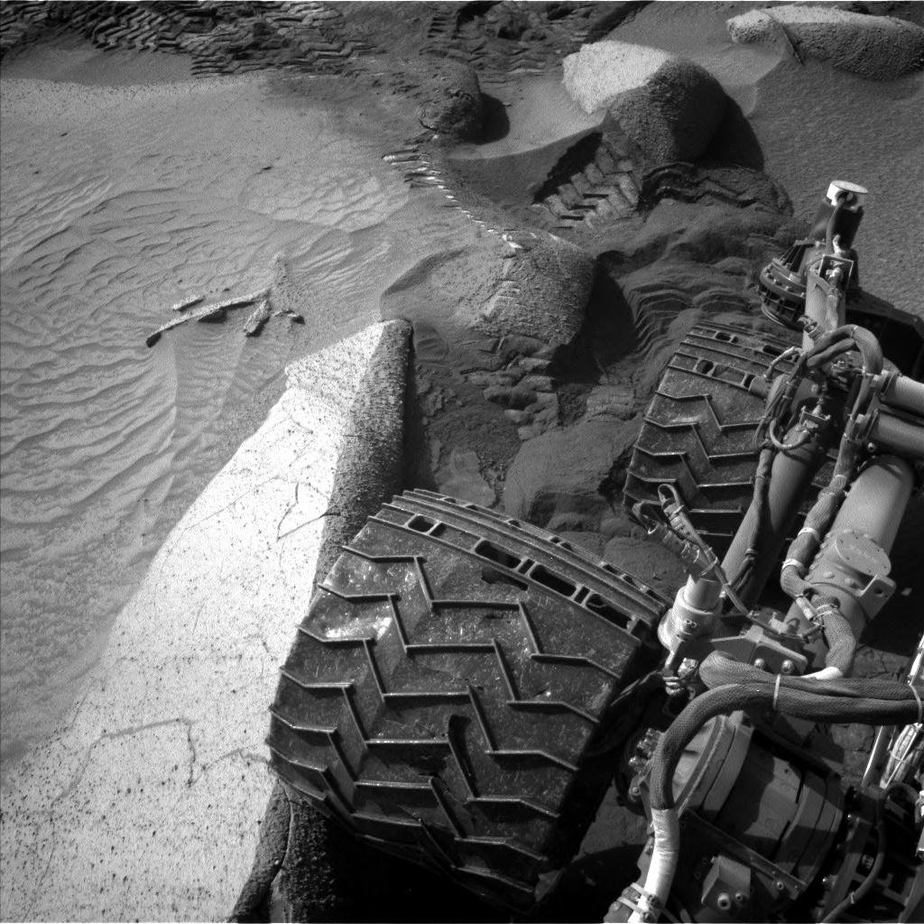
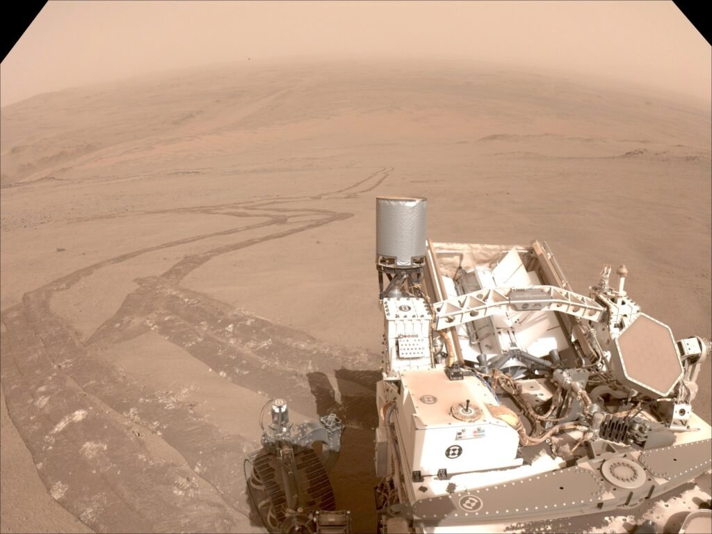
Planetary exploration rovers serve as essential tools for advancing scientific investigations, but their mobility is significantly challenged by loose and deformable surfaces like lunar dust and Martian regolith. These extraterrestrial terrains exhibit low cohesion and bearing capacity, leading to excessive wheel slip where the wheels rotate without generating sufficient forward motion.
As we dive deeper into autonomous space robotics here on Beyond the Joystick, I am realizing that mastering rover slip estimation is just as critical as orbital mechanics. If a rover cannot detect slip, standard wheel odometry accrues massive errors, causing deviations from planned trajectories and increasing the risk of entrapment. To understand how engineers solve this, we are going to explore how academic researchers utilize a single-wheel testbed to analyze wheel-terrain interactions before the software ever leaves Earth.
The Hardware: Inside a Single-Wheel Testbed
To develop accurate rover slip estimation models, engineers rely on single-wheel testbeds to isolate wheel-soil interactions, allowing for precise sensor mounting and controlled experimentation. The physical architecture of a modern testbed consists of several specific hardware components:
- The Frame and Sliding Carriage: An alluminio frame houses a moving carriage connected via linear bearings, enabling free motion in horizontal and vertical directions.
- Motorized Wheel with Encoder: The setup utilizes a wheel driven by a DC motor equipped with a high-resolution encoder to measure shaft rotation and velocity.
- Load Cell Integration: Mounted above the motor and wheel, a load cell measures the exact weight falling on the wheel to simulate specific gravity conditions.
- Onboard Camera: A downward-facing camera observes the wheel and soil movement directly, providing the visual data required to perform on-board slip estimation. In the lab, researchers often use river sand as a practical, reproducible substrate to simulate lunar regolith.
The Core Logic: Optical Flow vs. Angular Velocity
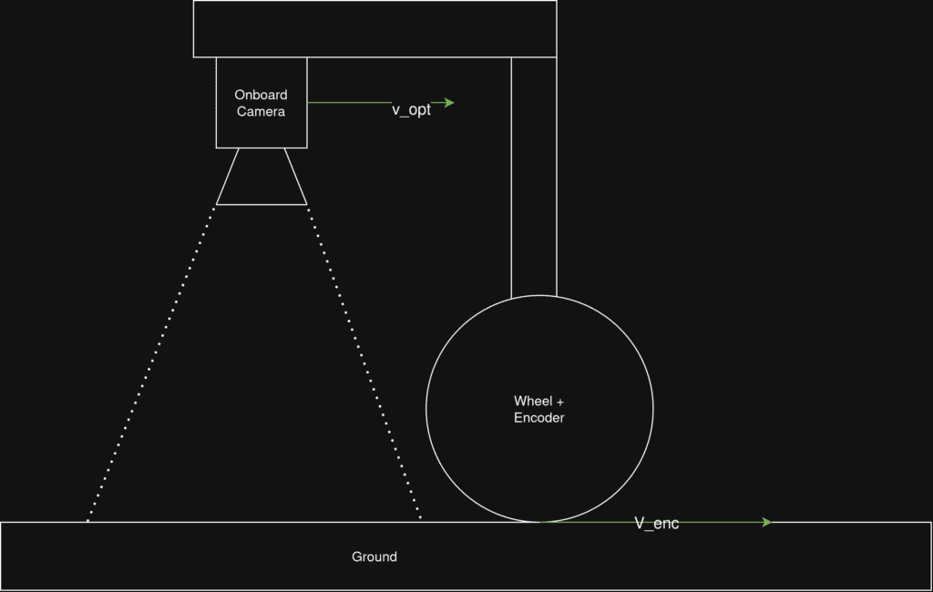
The fundamental mathematical principle behind rover slip estimation involves comparing two independent velocity vectors. The algorithm must identify disparities between the data from the wheel encoder and the on-board camera.
First, we process the encoder data to compute the angular displacement, which is then converted into tangential velocity (v_{enc}). This is calculated using the angular velocity (\omega) and the wheel radius (r):
v_{enc} = \omega \cdot rSimultaneously, the actual linear velocity (v_{opt}) is derived from the onboard camera. The system employs the Lucas-Kanade optical flow algorithm to compute pixel displacement per frame, translating image data into a physical metric velocity.
To quantify the traction loss, we calculate the slip ratio (s), defined as the difference between the tangential velocity and the linear velocity, normalized by the maximum of these two:
s = \frac{v_{enc} - v_{opt}}{\max(v_{enc}, v_{opt})}When v_{enc} > v_{opt}, the slip ratio is positive, indicating driving conditions where the wheel is slipping against the regolith.
Bridging Hardware and Software: The ROS 2 Architecture
Transitioning from theoretical physics to actionable autonomy requires a robust software stack. As someone who spends hours configuring Docker containers and ROS 2 communication layers for the PoliSpace drone team, I find the architecture of these rover testbeds incredibly familiar and highly effective.
The testbed framework integrates an embedded microcontroller with a high-level control system:
- Low-Level Acquisition: An Arduino Mega interfaces with the motor drivers, encoders, and load cell. It continuously acquires sensor data and transmits this telemetry over a serial connection in a lightweight JSON format.
- High-Level Processing: The high-level control layer is implemented using ROS 2 Humble. A Sensor Data Node parses the JSON messages and publishes the encoder counts and load cell readings as ROS topics. Simultaneously, a Motor Control Node publishes PWM commands back to the Arduino to adjust motor speeds.
This modular architecture allows a separate visualization node to display real-time wheel dynamics and load responses seamlessly.
The Results: When Incline Beats Traction
To validate the slip estimation algorithms, researchers command the motor to rotate to a fixed position across different terrain inclinations.
- Flat Terrain (0°) and Slight Incline (4°): The optical flow-based data shows good agreement with the encoder-based data. The slip ratio remains relatively low, staying below 0.2, indicating that the wheel maintains excellent traction.
- Moderate Incline (7°): The terrain dynamics shift dramatically. There is significant deviation between the two velocities, with the carriage covering less than half the expected distance. The average slip ratio increases significantly to approximately 0.5 (50% slippage).
- Critical Incline (15°): The incline completely defeats the wheel’s traction. The carriage barely moves any distance, suggesting total slippage and wheel sinkage. The calculated slip ratio approaches 1, indicating a critical loss of mobility.
Conclusion: From the Lab to the Moon
Accurate rover slip estimation is essential for ensuring reliable traversal and improving rover autonomy. By integrating encoders, load cells, and optical flow sensing into a single-wheel testbed, we can accurately quantify slip and study the complex mechanics of wheel-terrain interactions.
These empirical findings serve as the foundation for developing machine learning-based slip prediction and adaptive control algorithms, ensuring the success of future missions on challenging extraterrestrial terrains. With my upcoming internship focusing on exactly these ROS 2 slip-detection architectures for lunar rovers, analyzing these laboratory dynamics provides the perfect primer for the engineering challenges ahead.

Lascia un commento